Copyright (c) 2005, The Jhai Foundation.
Permission is granted to copy, distribute and/or modify this document
under the terms of the GNU Free Documentation License, Version 1.2
or any later version published by the Free Software Foundation;
with no Invariant Sections, no Front-Cover Texts, and no Back-Cover
Texts.
GNU Free Documentation License
Assembling a Jhai PC
This
is the Documentation on how to assemble the JPC, it is divided
into two sections. The first section is devoted to the assembly of the
JPC PC104 stack, and the second section is devoted to the assembly of
the JPC box.
Section 1: Construction of the Jhai PC 104 stack
Parts and Tools
List of Materials for the construction of the JPC PC 104 stack.
- 1 PC/104 PCMCIA module
- 128mb SDRAM
- PC/104 NS Geode GX1 300MHz single board Computer
- CISCO Aironet 350 Lan Adapter
- PC/104 Power supply
- 8 brass stand-offs
- 64-pin bus extender
- 40-pin bus extender
- 2.2 GB Microdrive
tools
needed
- Jewelers Phillips screw driver
- Number 2 Phillips screw driver
- Soldering iron
- 60/40 tin/lead solder with flux core
- VOM multimeter
Beginning steps for the construction of the JPC PC104 stack
- Slide the 128MB SDRAM module into the PC/104 NS
Geode GX1 300mhz single board Computer gently until
it clicks into place.

The SDRAM module clicks into place.

This is how it shall look when the SDRAM is properly seated.
- Gently slide the 2.2GB Microdrive into the PC/104 NS geode Gx1
300MHZ single board computer
until it clicks into place.

The Microdrive should slide in and fasten into place.

This is how it should look if the microdrive is seated properly.
- Slide the Cisco Aironet 350 Lan Adapter into the lower slot of
the PC/104 PCMCIA module.

The Cisco Aironet should slide easily into place and click.


This is how the Cisco airnet card should look if properly seated.
- Screw into place six brass stand-offs on to each
bottom corner of the PC/104 NS Geode GX1 300mhz
single board computers.

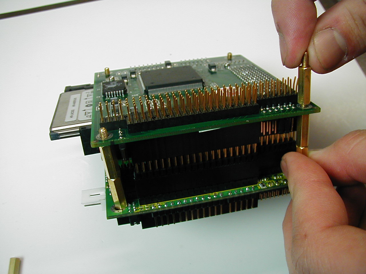
Screw brass stand offs together to form the legs of the PC/104
stack

Image of a completed PC/104 stack

More images of stands off being screwed in
- Slide carefully over the corresponding pins the
64-pin and the 40-pin bus extenders to the PC/104
PCMCIA module.

The bus extender should mate with the pins on the PC/104 PCMCIA
module bus
- Attach the PC/104 NS Geode GX1 300MHZ single board
Computer to the top of the PC/104 PCMCIA module.

The PC/104 PCMCIA module stacked on the PC/104 Powersupply

The PC/104 NS Geode GX1 300MHZ attached to the top of the stack
- Screw 4 brass stand-offs to the bottom of the
PC/104 PCMCIA module.

The PC/104 Power supply should fit snuggly on the bottom of the
stack.
- Attach the PC/104 Power supply to the bottom of
the PC/104 PCMCIA module by screwing 4 brass
stand-offs to the bottom of the PC/104 Power supply.

Four Brass stand-offs screwed to the bottom of the stack act as
feet.

Bottom view of thr completed PC/104 stack.

Side view of the completed PC/104 stack.

Top view of the completer PC/104 stack.
Section 2: Construct the JPC itself.
1
Plastic plate for the Vonage Linksys Router.

The plastic plate used to hold the vonageboard.
2 Terminal Blocks with 8 position jumper strips.

10 position terminal blocks.
Top and bottom of the JPC itself, the box.

Bottom part of the JPC case

Top part of the JPC case
1 Earth LCD with VGA cable and altered Power in cable with Spade
connectors.

Converted VGA power jack

VGA cable
6 inch RJ45 cross-over cable.

6 inches crossover cable and pc/104 LAN adaptor
1 pigtail with MMCX and TNC bulkhead connector.

Pigtail
1 Rotary switch.
1 Toggle switch.

Toggle switch
1 power jack
Screws needed in the JPC
- Top case: 6 x 4-40 x 3/8"
- Bottom case: 6 x 6-32 x 3/80"
- Keyboard: 2 x 4-40 x 1/2"
- Mouse: 2 x 4-40x 1/2"
- Analog
phone: 4 x 6-32 1/20"
- Terminals 4 x 6-32 x 3/8"
Note:
- The 104 Power supply runs on 12v's coming in from the terminal bus.
- The Vonage Box Linksys router takes 16 VDC, 8/5 AC.
Terminal bus solution to suppress high frequency
Materials
- 2 20 turns coils

Image of all the parts needed for the Power conditioning
circuitry. From the upper left the two 20 turn
coils,100 micro farad 50v cap,clamping diode, 2V025 metal Oxide Varistor,
and 1 mylar cap.
- 2V025 metal Oxide Varistor
Assembling the JPC box
- Install rubber Gramet into lower center hole on the JPC bottom
case. This is the VGA power in.
- Screw into place the VGA connector, Mouse/Keyboard, LP1, RJ11, AC
in jacks into the back of the bottom case. Will use
Locktite or nail polish in final construction to hold in place the
screws and nuts.
- Use 4 x 6-32 x 3/8 inch screw to attach the two bus terminals to
the bottom case.

Screwing in of the terminal bus
- Use machine screws to attach the Plastic plate for the Vonage router onto
the bottom of the JPC case.

Attaching plastic plate for the Vonage router onto bottom of the JPC case.
- Use 4 x 6-32 1/2 inch screws to attach the Linksys Vonage router
onto the Plastic plate.

Laying plastic brace in place

Screwing Linksys router in place
- Attach the Completed PC 104 stack to the bottom of the JPC case
with the four nuts and four washers provided.

PC/104 stack set in place

Nuts being attached to ther bottom of the stand offs

Nuts being tighted with needle nose plyers
- Slide and screw in place on the TNC/ N anttena connector and
attach to the PCI network card on the right hand or case side of the
card. This is Position 1, or primary anttena.

N connector with TNC convertor
- Attach the power toggle switch to the first hole on the right
front of the JPC case.

The toggle switch being installed

Toggle switch install on the upper right hand side of the case
- Attach the timer switch to the third hole on the right front of
the JPC case.

view of the back of the timer switch being set in place.

view of the front of the timer switch being in place.
- Attach the dial to the front of the timer switch.

Sliding the dial onto the front of the timer switch
Wiring of Terminal bus solution to suppress high frequency
- Attach the 100 micro farad 50v cap (blue) with 4933 surge
clamping diode.
- Attach the metal oxide varistor with the 1 micro farad cap.

The 2v250 and the 1 mylar cap together
- Attach the two 20 turn coils on the positive terminal bus on
either side of the suppression componations.

20 turn coil being installed to the terminal bus

Wiring of the toggle switch
- Attach the O-ring connector end of the first wire which
positive
to position 8 on the terminal block. This is the positon shared with
the 2nd 20 turn coil.

Shows the position shared with the 20 turn coil and the first
positive wire of the toggle switch.
- Attach the second wire which is positve to position 4 on the
positive terminal block.

Wire attached to position 4 on the positive terminal block.
- Attach the third wire which is negative to postion 3 on the
negative terminal block.

Shows the thrid and negative wire being installed on the
negative terminal block
Wiring of the timer switch
- Attach the Line1 wire to positon 3 on the positive
terminal block.

An image of the first Line of the timer switch being attached
to position 3 on the positive terminal block.
- Attach the Load1 wire to position 1 on the positve terminal
block.

An image of the load1 wire being attached with the positive VGA
power wire to the positive position one on the terminal block.

An image of the fully wired terminal block
Closing and powering on the JPC
- First before anything elese double check all of the wire and
terminal bus connections
- Making sure all of the wires are secure and out of the way
slide the top of the JPC case onto the bottom

Shows two hands gently sliding the top of the JPC onto the
bottom case.

The top is completly on and secure. You can now use the 6
screws to seal the JPC case.
- Place the LCD monitor onto the top of the case and tighten the
nuts
into place

show the process of installing the three nuts onto the LCD
screen.
- Plug the VGA power in jack into the back of the LCD screen.

The VGA power in jack plugs in right below the VGA cable
connector.
- Plug in the VGA plug into the jacks on the LCD screen and the
JPC case.
- Plug in the Keyboard and mouse into their PS/2 slots.

The keyboard jack being plugged in

The mouse being plugged in
- Connect the Printer
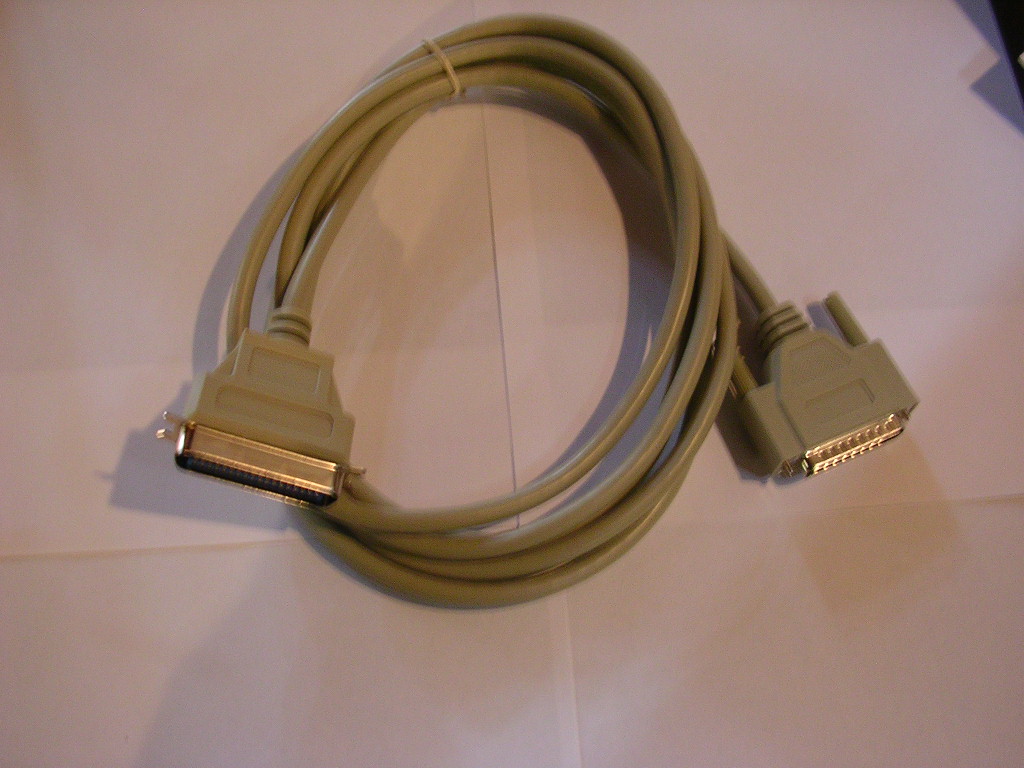
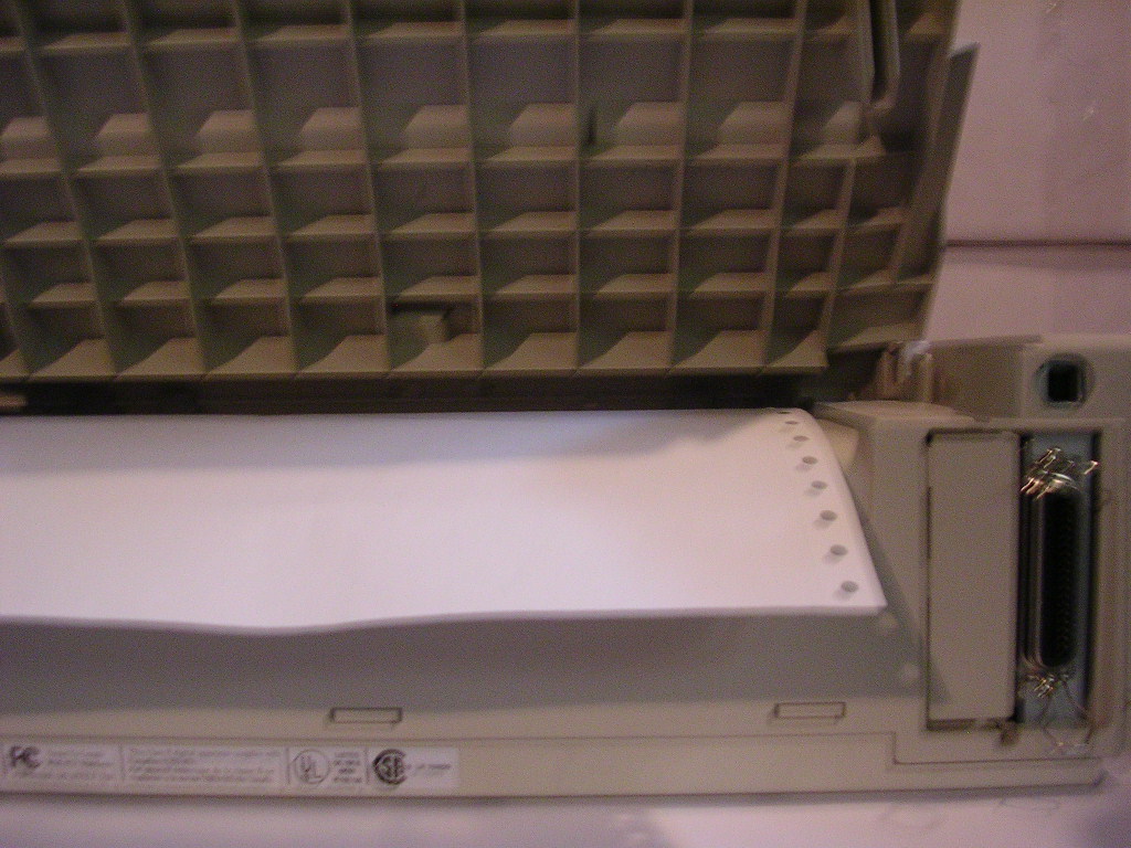
Connect the Parallel cable to the back of the printer

The Parallel cable

Image of the back of the printer

The Parallel cable being plugged into the back of the printer
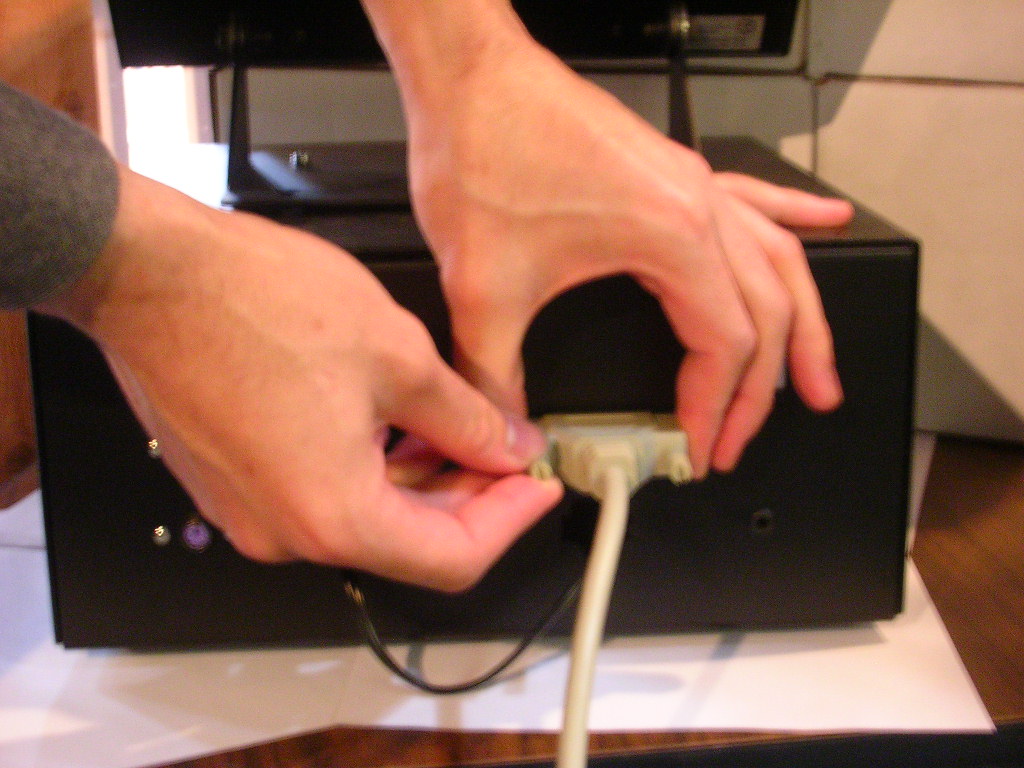
Plug the Parallel cable into the back of the Jhai PC

The Parallel cable being plugged into the back of the Jhai PC
- Plug in the outside power supply with the into the 12v power
jack.

A working complete JPC system


